

TSTN-060
Calibration Flatfield Projector#
Introduction#
The Flatfield Projector is part of the Rubin Calibration System, TSTN-066.
Like most observatories, Rubin Observatory uses a flatfield system to generate calibration products. Because the Rubin optical system is so fast (f/1.2) and the calibration screen is correspondingly large (10.27 m in diameter), the observatory uses a dedicated projector system to fill the screen with flat, homogeneous light at the ~f/4 beam speed required to match the reflector and screen geometry.
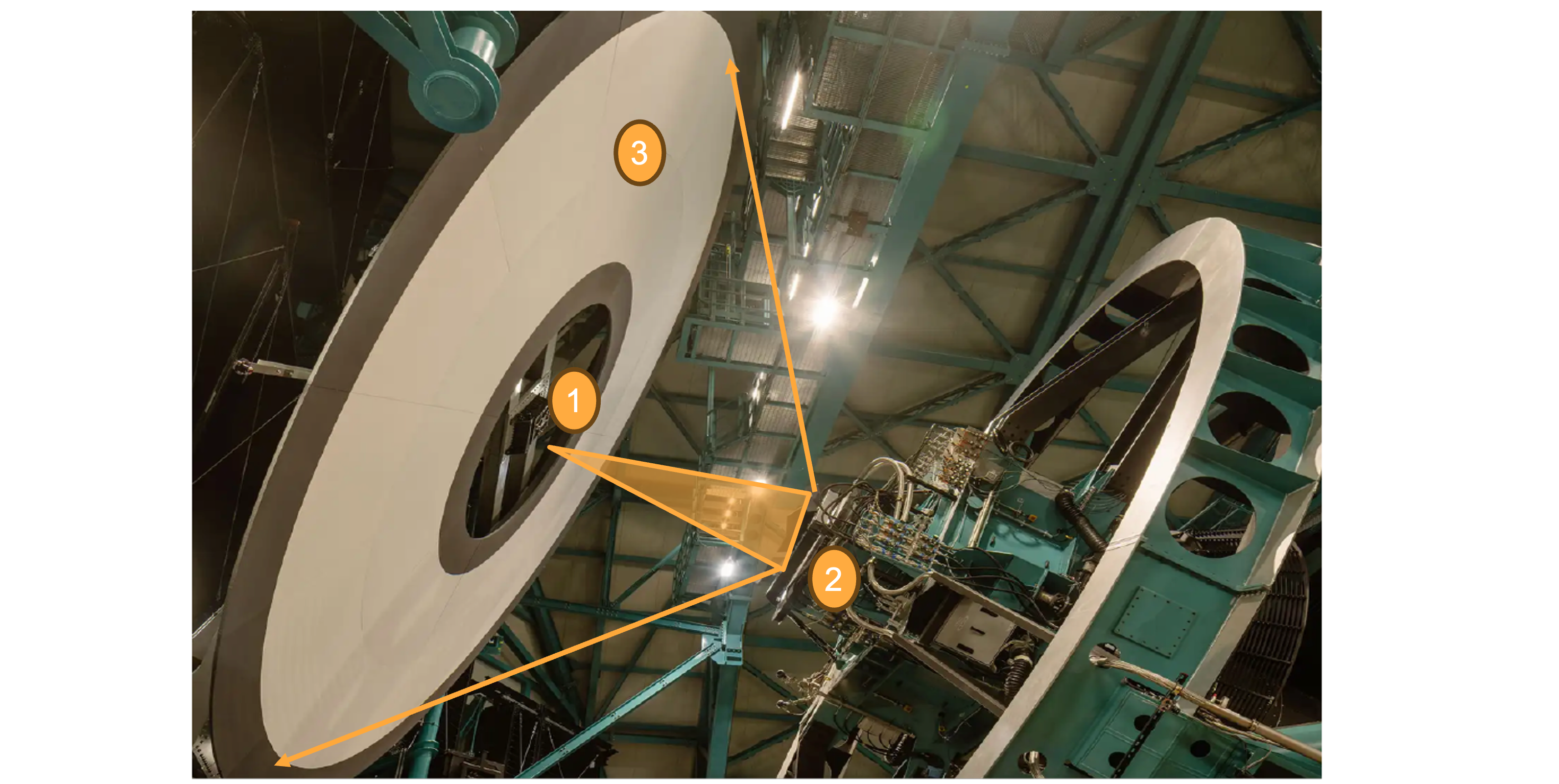
Fig. 1 The flatfield system, with the flatfield projector mounted in the center of the calibration screen. (1) is the flatfield projector, and the beam travels to (2) the reflector and then to (3) the calibration screen.#
The projector has two illumination modes: broadband, or whitelight, and monochromatic. The whitelight flats are produced using a set of bright LEDs and can be used daily to monitor the state of the camera. The monochromatic flats are generated using a tunable laser system (Ekspla NT242, with an Ekspla NT252 as backup). This produces light with a linewidth of ~1 nm FWHM, tunable across the full LSST operational wavelength range of 320-1125 nm (the underlying laser hardware covers 300-2600 nm). Mono flats help us measure the wavelength-dependent throughput of the optical system, including the filters, mirrors, lenses, and detector quantum efficiency.
The projector and its illumination sources must also satisfy demanding photometric requirements: spatial illumination uniformity better than 10% across the illuminated field at all operational wavelengths, a minimum spectral radiance of 3 mJy arcsec⁻² at the focal plane, and relative-flux monitoring precision of 0.2% RMS in the grizy bands and 0.3% RMS in the u band during a single exposure.
This tech note describes the flatfield projector itself, its mechanical and optical design, monitoring instrumentation, and operation. It does not include a detailed description of the tunable laser or its environmentally-controlled enclosure, which are covered in TSTN-065. Additionally, the calibration screen is covered in TSTN-057 and the reflector is covered in TSTN-049. The Flatfield Projector Electronics Cabinet is further detailed in TSTN-042.
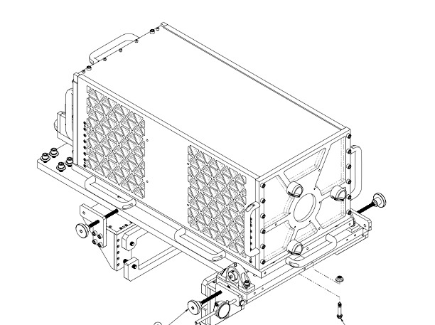
Fig. 2 Flatfield Projector shown with its mounting hardware. The drawing shows the exit aperture at the front.#
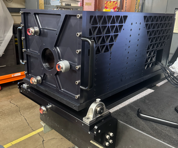
Fig. 3 Projector picture in Tucson shop during alignment.#
Mechanical Design#
The enclosure was conceptually designed by Parker Fagrelius and the mechanical design was completed by Brian Johnson. It was built in the NOIRLab Tucson shop, led by Ron Harris, and completed by Anthony Tache and Anthony Borstad. The drawings for the projector can be found on Docushare Collection-15446. In some places it is referred to as the Central Calibration Projector System (CCPS).
The enclosure for the projector is significantly constrained by the volume available within the calibration screen structure: the full assembly cannot exceed an envelope of 500 mm x 500 mm x 800 mm, positioned at the center of the screen. In addition to this tight volume constraint, the enclosure needed to be adjustable in tip/tilt and in both the X and Y directions in the plane of the screen, so that it could be precisely aligned with the calibration reflector and the telescope optical axis.
Built primarily from aluminum and light-weighted where possible, the assembled projector has a total mass of approximately 115 kg (250 lbs).
Because the overhead crane in the dome cannot reach the calibration screen position, the projector was raised from the observatory roof and pulled into the aluminum calibration screen frame during installation. Because of this, removal and replacement of the projector box is to be avoided once installed; the top, front, and back panels are removable instead, so that maintenance work can be performed in place from a lift (see also Access).
The projector was installed by first positioning a base plate using a Leica AT960 laser tracker. The projector enclosure was then slid into place on integrated steel ball bearings and secured with two bearings that allow tip adjustment; elevation alignment is provided by a screw assembly at the rear of the enclosure. Spherically Mounted Retroreflectors (SMRs) located on the projector base and around the output aperture allow laser tracker measurements to be used to align the projector precisely with the reflector (see Installation and Alignment).
The primary mechanical challenge of the design was integrating both the broadband and monochromatic optical projectors into the same enclosure while still allowing switching between them. The design has three main components: the LED module, the LED projector, and the laser projector. The LED and laser projectors are combined into an “optics module”. The LED and optics modules incorporate Linear Stages to move between projectors and filters.
Linear Stages#
There are several linear stages used in the projector to make sure that everything can fit. They are all from Zaber and are for the most part daisy chained together. They will be referred to throughout this document, so they are summarized here.
CSC Name |
Name |
Type |
Description |
|---|---|---|---|
LinearStage:101 |
LED Focus |
LSA25-T4A |
25mm of travel. The 90 degree mirror sits on top of this stage. |
LinearStage:102 |
LED Select |
X-LRQ300AL-DE51C |
300 mm of travel. 5 Multi-LED assemblies sit on this |
LinearStage:103 |
Vertical Select |
X-LRQ150HP-DEC51C |
150mm of travel. Both LED and Laser projectors sit on this. It is moved to align with the output aperture |
LinearStage:104 |
Laser Focus |
X-LSM050-E03 |
50 mm of travel. The controller for this was replaced. |
Optics Module#
The main challenge for this part of the design was fitting both the whitelight and monochromatic optical systems into the same box and being able to switch between them. The LED and laser projectors are combined into an “optics module,” mounted on a vertically oriented Zaber linear stage (“Vertical Select”).
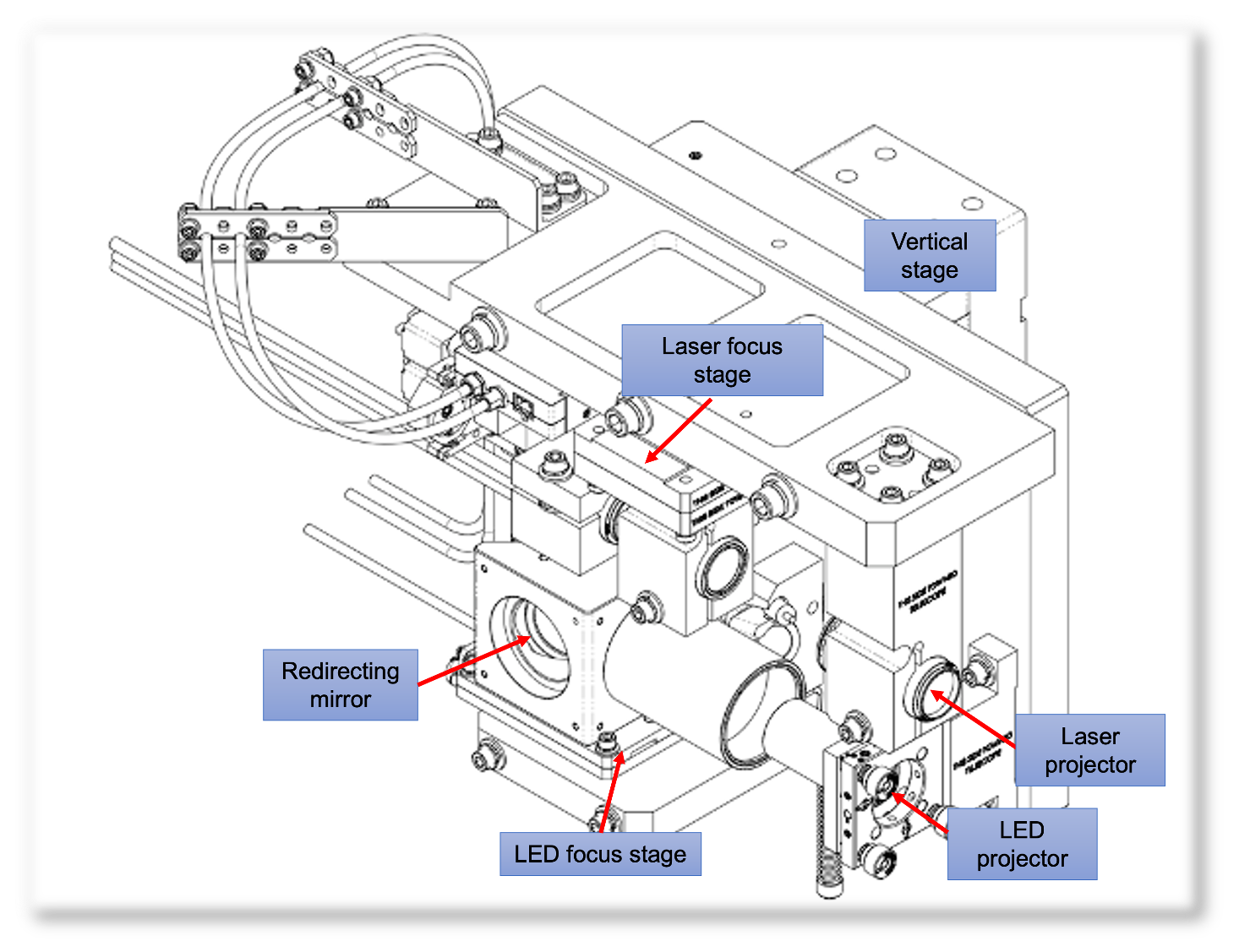
Fig. 4 Optics module for the projector.#
The laser projector sits on top and the LED projector is below, separated by 70mm. The vertical stage can be moved so that the output of either the laser optics or the LED optics is aligned with the output aperture. The values for the Vertical Select linear stage are:
Laser: 79.96 mm
LED: 9.96 mm
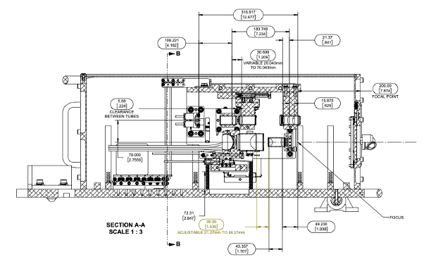
Fig. 5 Key spacing for the optics module optics.#
The 20 m fiber from the tunable laser is routed directly to a fiber gimbal (Zaber OMG-T4A) mounted on the optics module, so that the fiber can be better aligned. One of the optics in the laser optical path sits on a small Zaber stage (“Laser Focus”) that can be moved to adjust the separation between lenses, which is needed for focus and varies with wavelength. The remaining laser-path lenses are fixed directly to the optics module, with the focus point located 200 mm behind the output aperture.
Due to interference between the connectors for the Laser focus stage and the LED modules, this stage was modified by our team: the controls were separated from the stage itself and mounted with a bracket, so that there is no longer any interference. As a result, the as-built stage no longer matches the original drawing above; it was damaged and replaced with the modified version in October 2025.
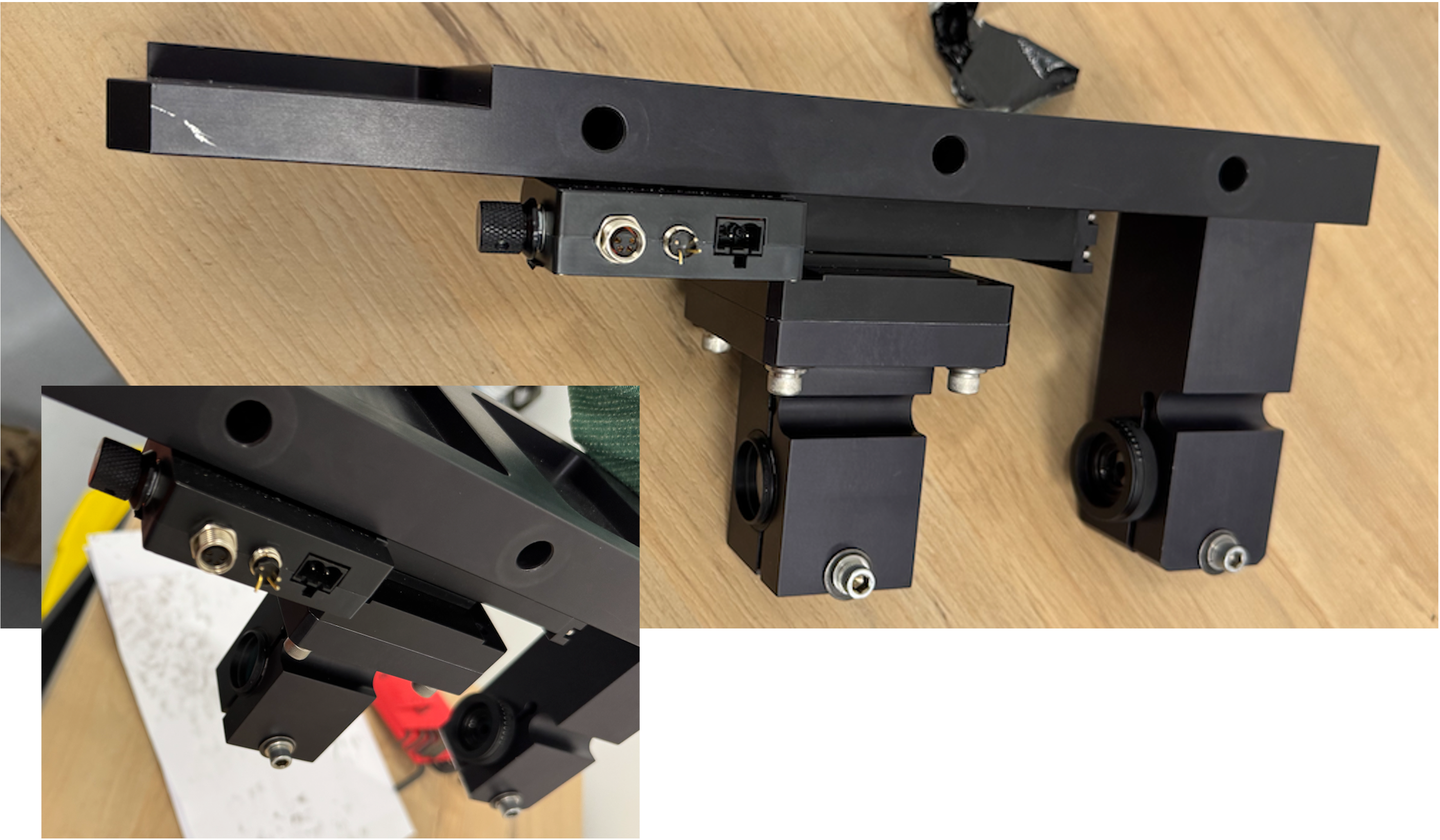
Fig. 6 Damaged Laser Focus linear stage controller. The connectors broke off completely#
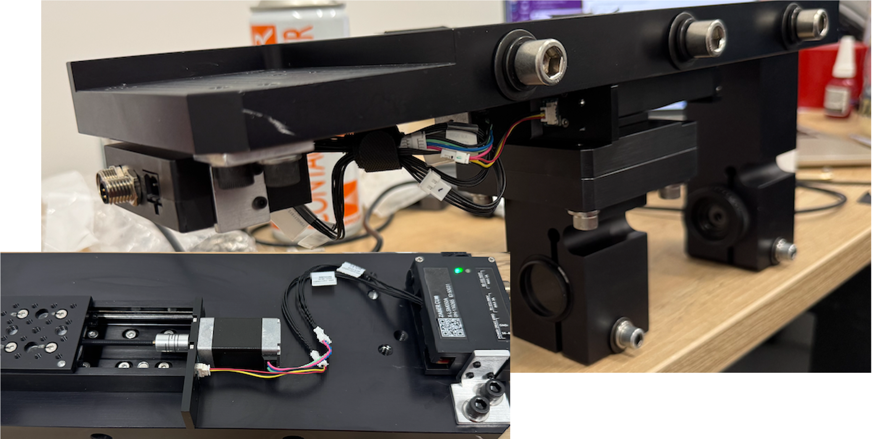
Fig. 7 Replaced version of the Laser Focus controller, moved to the side so that the connectors no longer interfere. Rather than bolting directly to the linear stage, it is connected via a short cable.#
The whitelight optical path starts with aligning the Multi-LED module with the optics module. A mirror is used to redirect the light path to align with the output aperture. This mirror sits on a small Zaber stage (LED Focus) so that the distance between the optics following the collimating lens can be changed to account for focus. The LED projector stage also needs to be moved in coordination to account for these changes and maintain alignment.
The laser optical path is attached to the optics module with three long bolts, with shims used to maintain alignment with the output aperture. The components of the whitelight optical path are attached separately to the optics module.
Prior to shipment, the output beam from both the LED and laser projectors was characterized using a laboratory test setup that scanned a calibrated photodiode across the beam at the nominal 3.2 m working distance corresponding to the reflector location, both directly and reflected off the reflector itself. These measurements confirmed that the delivered beam speed matched the f/4 design specification across the tested wavelength range and provided a baseline against which in-dome commissioning performance has since been compared.
Photodiode Holder#
The projector system includes both a photodiode, read out via an electrometer, and two fiber-fed spectrographs, used to monitor the output light. Because we want to measure both the LED and laser light in the projector, the photodiode and spectrograph fibers are mounted within the projector enclosure facing the output aperture, where they collect light reflected back from the beam path. Some reflective tape was added in this area to increase the amount of reflected light available to the monitors. Further detail on the instruments themselves and their performance is given in Monitoring System.
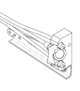
Fig. 8 Photodiode and Optical Fiber holder. This is secured very close to the Optics Module.#
Cable Management#
With the exception of the laser fiber gimbal (OMG-T4A) and the LED focus stage, all Zaber stages in the projector are powered and controlled via a daisy chain. This limits the cable run to the projector to three stage-control cables plus one individual control cable per LED. A 7 m optical fiber from each spectrograph and a BNC cable from the electrometer to the photodiode are routed up the back of the calibration screen structure to the electronics cabinet (see Electronics Cabinet).
Care has been taken within the projector enclosure to ensure that the LED control cables and the fibers and BNC cables do not interfere with the various linear stages. There are a variety of tie-downs inside the enclosure, and anytime a cable is removed or added, this must be taken into consideration.
Access#
Because the projector cannot be removed once installed (the overhead crane cannot reach the calibration screen position on the dome), all routine access is performed in place. The top, front, and back panels of the projector are removable so that work can be performed inside the enclosure from a lift. To remove the front panel, it is best to first install the red cover. This can be found in the optics lab on level 5. Then unbolt the 12 bolts on the sides of the front panel, which are all captive. The front is held in place also by a single pin on the bottom.
From the front, you should be able to remove the optics module if needed.
The top panel is quite light. It needs to be remove by two captive screws in the back and then slid out.
The back panel can also be removed in the same way as the front panel.
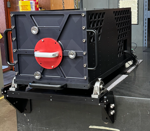
Fig. 9 Projector with the red cover installed to protect the output aperture. This should be installed before removing the front panel.#
Optical Design#
Both the LED and laser projectors are required to output an ~f/4 beam at precisely 3.2 m from the apex of the reflector, filling the reflector so that light is projected onto the calibration screen as a flat pupil image. The optical prescriptions for both paths are designed so that the output beam speed remains ~f/4 across the full operational wavelength range using focus-compensation stages.
The details of the optical design for both were considered in the Flatfield Exposure Time Calculator, which can be found in SITCOMTN-049.
Whitelight Projector#
LED Module#
The whitelight/LED module is made up of 10 Thorlabs LEDs, covering the six LSST ugrizy filter bands, paired into five two-LED modules using dichroic beam combiners, based on this idea from Thorlabs.
There are 5 combinations. Two LEDs are combined per dichroic for the g, r, i, and z bands to improve spectral coverage within each filter’s bandpass, while the u- and y-band LEDs are not used together but share a single dichroic to reduce the overall size, with only one of the two active at a time.
These Multi-LED modules are all mounted on the LED Select Zaber linear actuator, oriented perpendicular to the output aperture. The stage itself was modified so that the platform could be bolted to it. The linear stage translates so that each Multi-LED module can be brought into alignment with the LED projector optics. A 90-degree fold mirror then redirects the beam toward the output aperture, and a small Zaber stage (LED Focus) beneath this mirror allows the downstream optical path length to be adjusted for focus, with the LED projector stage moving in coordination to maintain alignment.
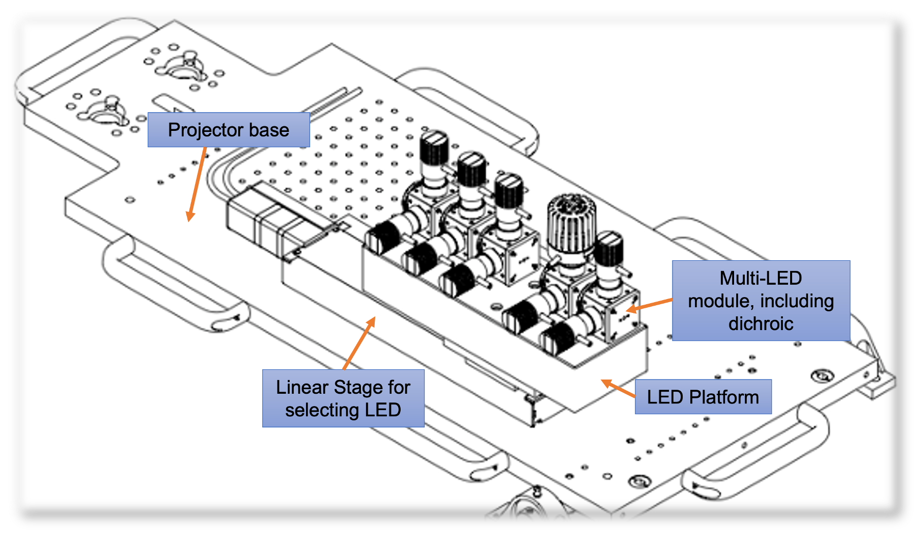
Fig. 10 LED Modules mounted on the LED Select Linear Stage. In this drawing, one of the LEDs appears to have a different form factor. We have actually swapped that out, so all the LEDs now have the same form factor.#
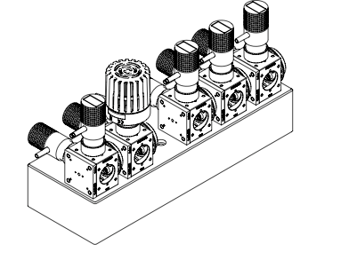
Fig. 11 Two LEDs are mounted, with a collimating optic, to a Thorlabs Cube. Inside the cube, the dichroic is mounted, which will reflect light from one LED and transmit the others.#
Whitelight Optical Model#
The LED beam profiles vary significantly depending on the physical construction of each device — some LEDs are encased in a dome of glass or plastic, while others have a flat emitting surface — so the distance to the collimating lens had to be carefully measured for each individual LED, varying by up to 0.956 mm between the u-band and infrared LEDs. The same collimating optic (Thorlabs ACL2520U) is used for all LEDs, differing only in the AR coating selected for each wavelength.
After collimation, each LED beam passes through a dichroic beam combiner paired with one other LED of the same filter band. From the dichroic, the beam is redirected 90 degrees by a fold mirror and expands slightly over a 170 mm path, after which an intermediate pupil image is formed by a Thorlabs ACL5040 lens. A pupil stop at this point, 6 mm in diameter, selects the flat top of the LED intensity profile. The separation between the collimating optics and the pupil can be adjusted by up to 2.8 mm using a linear stage to compensate for wavelength-dependent focus shifts. A subsequent ACL2520U lens and a 50 mm focal length lens then convert the beam to ~f/4. Positional tolerances between optics in the plane of the beam range from 0.058-0.152 mm, with 0.289 degrees to greater than 1 degree of tolerance in tip/tilt.
You can find the details of the optical design, and its many iterations on confluence. The optical design was completed by Roberto Tighe.
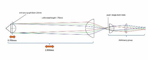
Fig. 12 LED projector optical design.#
Each LED has its own controller (Thorlabs LEDD1B), and the brightness of each can be independently adjusted so that the signal-to-noise for a given filter is comparable in a 30 second exposure.
LED |
Wavelength (nm) |
Filter |
Dichroic |
Collimating Optic |
SSR |
LabJack Pin |
LEDSelect |
LEDFocus |
|---|---|---|---|---|---|---|---|---|
M385L3 |
385 |
u |
DMLP735B^{*} (Thorlabs) |
ACL2520U-A |
1 |
EIO0 |
174.18 |
9.42 |
M455L4 |
455 |
g |
DMLP490 (Thorlabs) |
ACL2520U-A |
3 |
EIO2 |
5.925 |
8.57 |
M505L4 |
505 |
g |
DMLP490 (Thorlabs) |
ACL2520U-A |
4 |
EIO3 |
5.48 |
8.12 |
M565L3 |
565 |
r |
DMLP605 (Thorlabs) |
ACL2520U-A |
5 |
EIO4 |
67.14 |
7.79 |
M660L4 |
660 |
r |
DMLP605 (Thorlabs) |
ACL2520U-A |
6 |
EIO5 |
66.87 |
7.52 |
M730L5 |
730 |
i |
69904 (Edmund Optics) |
ACL2520U-B |
7 |
EIO6 |
233.91 |
7.15 |
M810L5 |
810 |
i |
69904 (Edmund Optics) |
ACL2520U-B |
8 |
EIO7 |
233.71 |
6.94 |
M850L3 |
850 |
z |
DMLP900 (Thorlabs) |
ACL2520U-B |
9 |
CIO0 |
295.61 |
6.85 |
M940L3 |
940 |
z |
DMLP900 (Thorlabs) |
ACL2520U-B |
10 |
CIO1 |
295.432 |
6.66 |
M1050L4 |
1050 |
y |
DMLP735B^{*} (Thorlabs) |
ACL2520U-B |
2 |
EIO1 |
171.24 |
6.47 |
LED Select and Laser Focus are the names of the control software constants associated with LED/stage positioning, referenced above. ^{*} The DMLP735B form factor is too large for the Thorlabs cube. This was cut in half by Gary Poczulp using a wire saw that uses 0.008” diamond wire (45um).
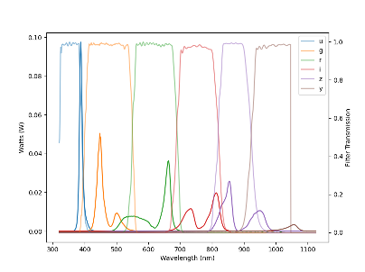
Fig. 13 Flux from the LEDs overlaid with the filter coverage.#
Operational experience during commissioning has shown that several LEDs are useful outside their originally assigned filter bands; for example, the redder z-band LED (M940L3) has been used for measurements through the y filter to optimize signal levels or spectral coverage, and out-of-band LEDs have proven valuable for identifying filter leakage and scattered light. For the u-band in particular, the narrow SED of the LED and its peak near the filter edge limit its effectiveness as a broadband calibration source; monochromatic flats from the tunable laser are therefore the primary means of calibrating the bluest wavelengths, and improving u-band whitelight coverage remains an area of future work.
It was also found during commissioning that alignment of the LEDs relative to the dichroics, combined with differences in LED shape and size, produced radial illumination gradients. Together with the non-overlapping LED SEDs, this made it difficult to weight the flats appropriately to match the color of the sky. As a result, each LED in a pair is now imaged individually, with the exposures combined in post-processing, rather than illuminating both LEDs of a pair simultaneously.
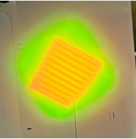
Fig. 14 You can see the output from two different LEDs. They differ in shape and size, making it difficult to fully “combine” them.#
Laser Projector#
The laser projector takes the output from an NA 0.03 fiber and produces an f/3.9 beam. Two lenses with f = 250.9 mm focal length (fused silica) collimate the fiber output, with the separation between them adjustable via the Laser focus linear stage to account for the wavelength-dependent impact on focus. The beam then passes through a pupil stop and two f = 39.86 mm N-BK7 lenses. The optical tolerances for this design are forgiving: positional tolerances between optics in the plane of the beam range from 0.122-0.179 mm, with greater than 1 degree of tolerance in tip/tilt. The focus point of the assembled laser path is located 200 mm behind the output aperture.
The output of the laser can be found in the Tunable Laser tech note TSTN-065.
You can find the details of the optical design, and its many iterations on confluence. The optical design was completed by Roberto Tighe.
Electronics Cabinet#
The electronics cabinet is mounted on the back side of the calibration screen structure, approximately 6 m below the projector. It houses the LED controllers, the Keithley electrometer, the Avantes spectrographs and their arc-lamp wavelength calibration source, the Zaber stage power supplies and controllers, a power distribution unit (PDU), and a Cisco network switch. A separate tech note goes into detail on the Electronics Cabinet TSTN-042.
Power is delivered to the projector electronics cabinet directly from the CBP electronics cabinet. There is a PDU in the electronics cabinet, which powers the electrometer, fiber spectrographs, and a series of other DC power supplies. Network connectivity is provided via fiber-optic cable from a switch that communicates wirelessly to the fixed portion of the dome; the link is optimized for the telescope park position, when the dome and telescope are co-aligned. The network switch gets its power directly from the power connection to the CBP so that the PDU can be communicated with.
Monitoring System#
The projector includes a NIST-calibrated photodiode read out by a precision electrometer (Keithley 6517B, operated in current mode), together with two fiber-fed spectrographs (Avantes AvaSpec-ULS3648TEC-USB2), with gratings selected to cover 250-850 nm (Grating BB) and 600-1100 nm (Grating IB) respectively, providing overlapping coverage across the full operational wavelength range. The resolution for both is 0.30-0.36 nm (FWHM).
The Electrometer is controlled through a serial server (Moxa 5450I) and the Fiber Spectrographs are each connected to their own embedded SBC computer. Details on access to these can be found in the electrical cabinet tech note TSTN-042.
The photodiode was calibrated against a NIST-traceable reference using a dedicated bench setup developed by colleagues at LPNHE (see their paper here). This procedure calibrated several Hamamatsu S2281 silicon photodiodes, one of which is deployed in the projector monitoring system (a second is deployed in the Collimated Beam Projector, CBP). Early commissioning results indicate a photodiode flux measurement precision of approximately 2% RMS in the grizy bands and 4% RMS in the u-band — both of which currently exceed the 0.2% and 0.3% requirements, respectively, by roughly an order of magnitude.
Commissioning of the fiber spectrographs was delayed by a throughput issue in the fiber runs between the projector and the electronics cabinet: the original configuration used two shorter fibers joined by a connector, which reduced throughput below acceptable levels. These have since been replaced with single continuous fiber runs, and full commissioning of the spectrographs is now underway; initial measurements indicate flux precision consistent with requirements, though work to improve signal-to-noise continues.
In the electronics, there is a spectrograph calibration lamp. In order to use this, one must travel up to the electronics cabinet and connect a fiber optic patch cord from the lamp to the spectrographs (one at a time). The fiber optical cables must be carefully removed during this process.
Alignment#
Uniform illumination of the camera requires that the projector, reflector, and calibration screen be mutually aligned and co-aligned with the telescope optical axis. The central requirement is that the reflector center be aligned with both the projector and the telescope optical axis to within 2 mm in position and 0.175 degrees in tip/tilt when the dome is in the calibration position.
The projector carries SMRs on its base plate and around its output aperture. These SMRs are usually removed, but can be replaced when needed. These are used together with SMRs on the reflector and calibration screen as fiducials for laser tracker measurement, enabling the position and orientation of each component to be measured in a common reference frame and verified after installation or any subsequent hardware intervention.
The projector was aligned to the telescope optical axis during installation using a Leica AT960 laser tracker. With the base plate positioned and the projector slid into place, tip and elevation adjustments were made using the bearing and screw assemblies described in Mechanical Design, with SMR measurements used to confirm the final alignment. This alignment can be reverified at any time using the same SMR fiducials, without needing to remove or disturb the projector.
Operations#
The flatfield projector can be used in either Whitelight or Monochromatic modes. To produce flats, the calibration screen needs to be aligned with the TMA and the Reflector covers must be open.
Control Software#
The main CSCs associated with the flatfield system are:
-
Electrometer:103 is for the Flatfield System
-
FiberSpectrograph:101 is the Red Spectrograph, and FiberSpectrograph:102 is the Blue Spectrograph
The operation of the calibration system in general is managed by MTCalsys, which can be found in ts_observatory_control/maintel/mtcalsys.py. The configuration for all the tests or sequences (i.e. sequence names) can be found in ts_observatory_control/data/mtcalsys.yaml.
Component GUIs#
For most troubleshooting, you will need access to some GUIs to communicate directly with the components:
Electrometer: Moxa can be accessed through a web interface at
flatfield-stages.cp.lsst.org.LEDProjector: These are controlled with a LabJack. You can use the Kipling GUI. This is downloaded on
laser-powermonitor.cp.lsst.orgwindows machine.LinearStages: These can be controlled with the Zaber Launcher App. This is also downloaded on
laser-powermonitor.cp.lsst.orgwindows machine.
Operational Procedure#
A typical sequence for performing flats would be:
Open mirror covers
Align Dome and TMA. Use the M1M3 laser tracker to do fine alignment
Open Reflector covers
Setup the Calibration Projector by moving the linear stages into place
Turn on the LEDs or Laser
Take flats with LEDs or scan through wavelengths with the laser
Park the projector
Close the Reflector covers
Maintenance#
Daily CalSys Checkout (Test Case BLOCK-T529) and Weekly CBP and Laser Checkout (Test Case BLOCK-T683) help us identify any issues with the Projector.
The optics need to be cleaned on a regular basis, with a basic cleaning of the aperture window quarterly. An advanced cleaning of all optics inside the projector is to occur two times per year. Maintenance procedures can be found here.
The photodiode will go out of calibration, so needs to be replaced with a NIST calibrated photodiode yearly. This will be done by shipping the photodiode to our collaborators at LPNHE.
Troubleshooting#
All troubleshooting documentation can be found on the Observatory Operations Documentation Confluence Pages for MTCalSys.